Block diagrams
It is a common practice to represent control system models by block diagrams. The graphical representation of systems with many components and intermediate signals helps the researchers have a better understanding on the system structure. The block diagram based representations are not only used to make the considered system comprehensible but also helpful during the design phase.
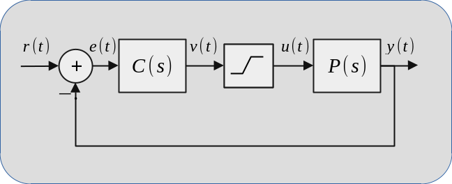
The diagram above shows a closed loop linear time-invariant (LTI) system with command saturation non-linearity. \(P(s)\) denotes the plant defined by a LTI transfer function, \(C(s)\) stands for the LTI controller. There is a non-linear block between these two which implies controller output is saturated meaning its magnitude can not be greater than a specific value. Lastly, the left most block is a subtractor.
One can observe the input (\(r(t)\)), output (\(y(t)\)) and intermediate signals flowing from one block to an other. Output measurement (\(y(t)\)) is subtracted from the reference input (\(r(t)\)) which creates the error signal (\(e(t)\)). The controller (\(C(s)\)) generates the command (\(u(t)\)) which is the saturated version of \((v(t))\) to drive the plant (\(P(s)\)).
The goal of this design is making output (\(y(t)\)) track the reference signal (\(r(t)\)). In other terms, the goal is making the magnitude of error signal (\(e(t)\)) zeros as time (\(t\)) goes to infinity.
As you can see, the figure above can explain what is considered better than the last paragraphs if you can read the diagram.
Spice simulator
Spice simulation software which dates back early 70s is a highly popular tool for representing and simulation interconnected components. It is developed with a focus on simulating electronic circuits and has several different implementations under different names. This article considers an open source implementation called NGSpice which provides XSpice backend that lets using several signal processing blocks in addition to the electronic circuit components.
XSpice can be used for simulating linear time-invariant (LTI) systems by using XSpice's int and poly models. XSpice models are defined by functions written in C language and compiled to a dynamical library which will be imported by NGSpice. This code-level model design lets the developer create performant models freely.
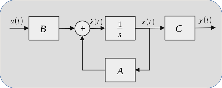
The plant, \(P(s)\), denotes an LTI system which is defined by a set of linear ordinary differential equations (ODE). It can be expanded to sub-blocks as shown below.
where
- \(u(t)\) is the input vector,
- \(x(t)\) is the state vector,
- \(y(t)\) is the output vector.
- \(\frac{1}{s}\) is the integrator that calculates \(x\) for given \(\dot{x}=\frac{dx}{dt}\).
In mathematical terms, the plant can be described by
$$\dot{x}=Ax+Bu$$
$$y=Cx$$
Theses equations consist of matrix-vector products and integration of vectors in the time-domain. Hence, creating a spice netlist by using XSpice's int and poly blocks is sufficient to simulate these two equations.
Aircraft model
The system simulated by NGSpice is the unstable aircraft model taken from [1]. The system matrices are defined as
$$A=\begin{bmatrix}-0.3220 & 0.0640 & 0.0364 & -0.9917 & 0.0030 & 0.0008 & 0 \\ 0 & 0 & 1.0000 & 0.0037 & 0 & 0 & 0 \\ -30.6492 & 0 & -3.6784 & 0.6646 & -0.7333 & 0.1315 & 0 \\ 8.5396 & 0 & -0.0254 & -0.4764 & -0.0319 & -0.0620 & 0 \\ 0 & 0 & 0 & 0 & -20.2000 & 0 & 0 \\ 0 & 0 & 0 & 0 & 0 & 0.0010 & 0 \\ 0 & 0 & 0 & 7.2958 & 0 & 0 & -1.0000 \end{bmatrix}$$
$$B=\begin{bmatrix} 0 & 0 \\ 0 & 0 \\ 0 & 0 \\ 0 & 0 \\ 20.2 & 0 \\ 0 & 20.2 \\ 0 & 0 \end{bmatrix} ~~~~ C=\begin{bmatrix} 0 & 0 & 0 & 57.2958 & 0 & 0 & -1.0000 \\ 0 & 0 & 57.2958 & 0 & 0 & 0 & 0 \\ 57.2958 & 0 & 0 & 0 & 0 & 0 & 0 \\ 0 & 57.2958 & 0 & 0 & 0 & 0 & 0 \end{bmatrix}.$$
The model is assumed to have an actuator failure which is modeled by an unstable pole in the state matrix \(A\). However, a static output feedback (SOF) gain is enough to stabilize the unstable aircraft. The SOF gain calculated by focont tool [2] is given below.
$$K=\begin{bmatrix} 0.1571 & 0.6951 & -1.6636 & 0.827 \\ 0.2387 & -0.0357 & 0.0461 & -0.0374 \end{bmatrix}$$
Overall closed loop system is shown in the block diagram below.
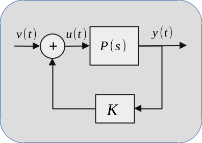
In the diagram, \(P(s)\) is the unstable aircraft model, \(y(t)\) is the model output. The output is multiplied by the gain \(K\) and the result is directed to input \(u(t)\). If the feedback loop is not used, any input causes the magnitude of output increase unboundedly as a result of unstability. However, the feedback gain \(K\) produces an input which limits this behavior.
Spice simulation
The unstable aircraft model is simulated in NGSpice by using its Kicad based graphical user interface. The model consists of three blocks
- \(P(s)\) dynamic system,
- \(K\) static gain,
- Summation block.
These blocks are generated by using kicadODE. This site provides a web interface for using kicadODE which saves the results under a cryptic URL for future use and lets user download spice model and the circuit symbol to be imported from Kicad. Three models given above can be downloaded from the links below.
- \(P(s)\): unstable_aircraft_model
- \(K\): unstable_aircraft_SOF_gain
- Summation: unstable_aircraft_fb_sum
These symbols can be imported into a Kicad schematic as explained in this page. Finally, a circuit structure can be built as shown in the image.
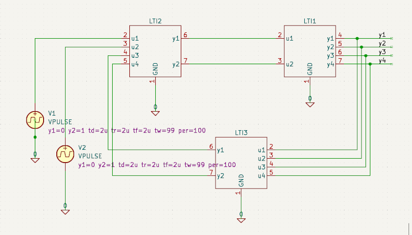
In the schematic above,
- LTI1 is the plant \(P(s)\),
- LTI3 is the SOF gain \(K\),
- LTI2 is the summation block.
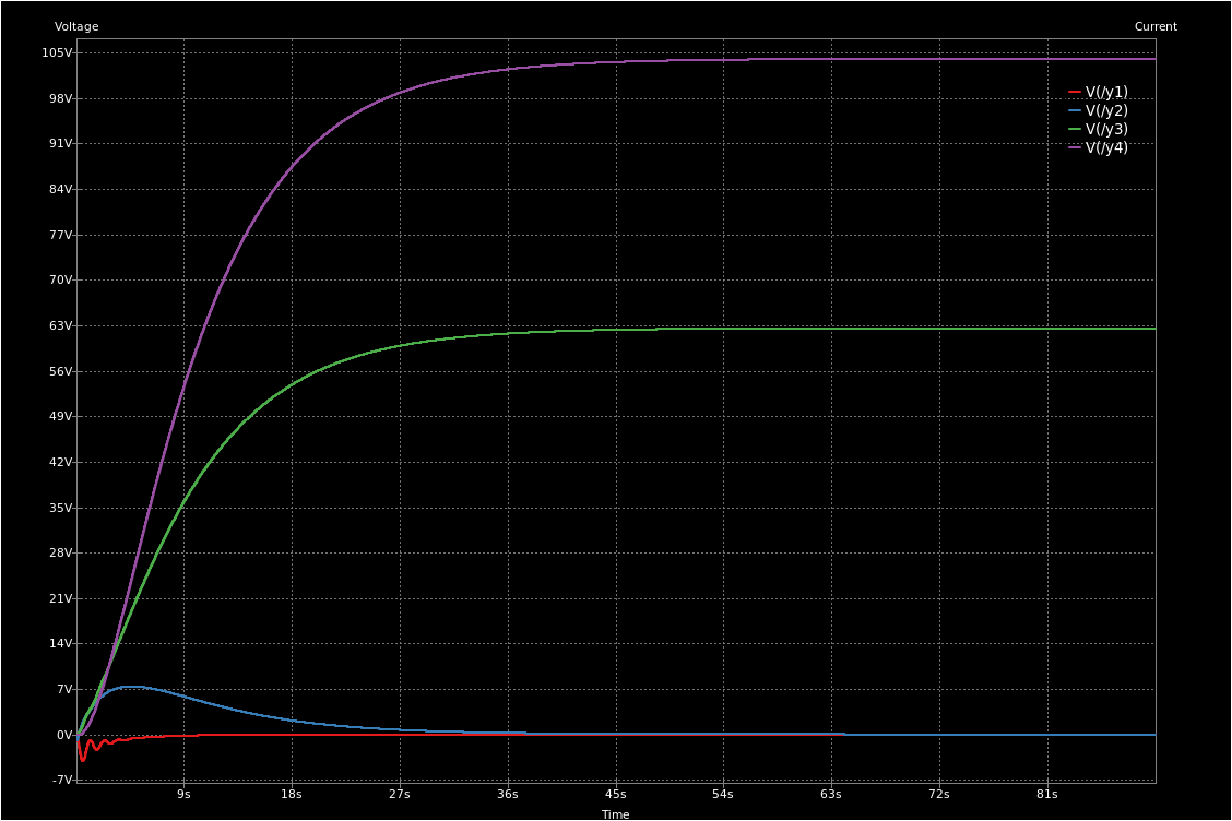
Voltage sources V1 and V2 are connected to simulate the step response. The simulation result is shown below.
Conclusion
Despite the wide adoption of open source libraries and tools in the research areas which deals with problems related to signal processing, statistics and optimization, the commercial tools like Simulink, Labview dominates the industry and academia when it comes to dynamical models and discrete-event systems simulations.
NGSpice is a decent open source alternative for implementing simulations. Its functionality can be expanded by developing Xspice models in C language. Xspice models has a well defined format and new models can be easily integrated into the NGSpice binaries.
Kicad introduces a fairly good graphical interface for users who do not want to manually write netlist files. This site has a tool to create ODE models and symbol files which can be imported to Kicad. An important future work would be to create graphical symbols for all Xspice models.